Bus pirate presentation
Hello people, for this first post, I wanted to make a small presentation of the bus pirate, which is a hardware tool I use a lot in my experimentations on IoT.
Overview
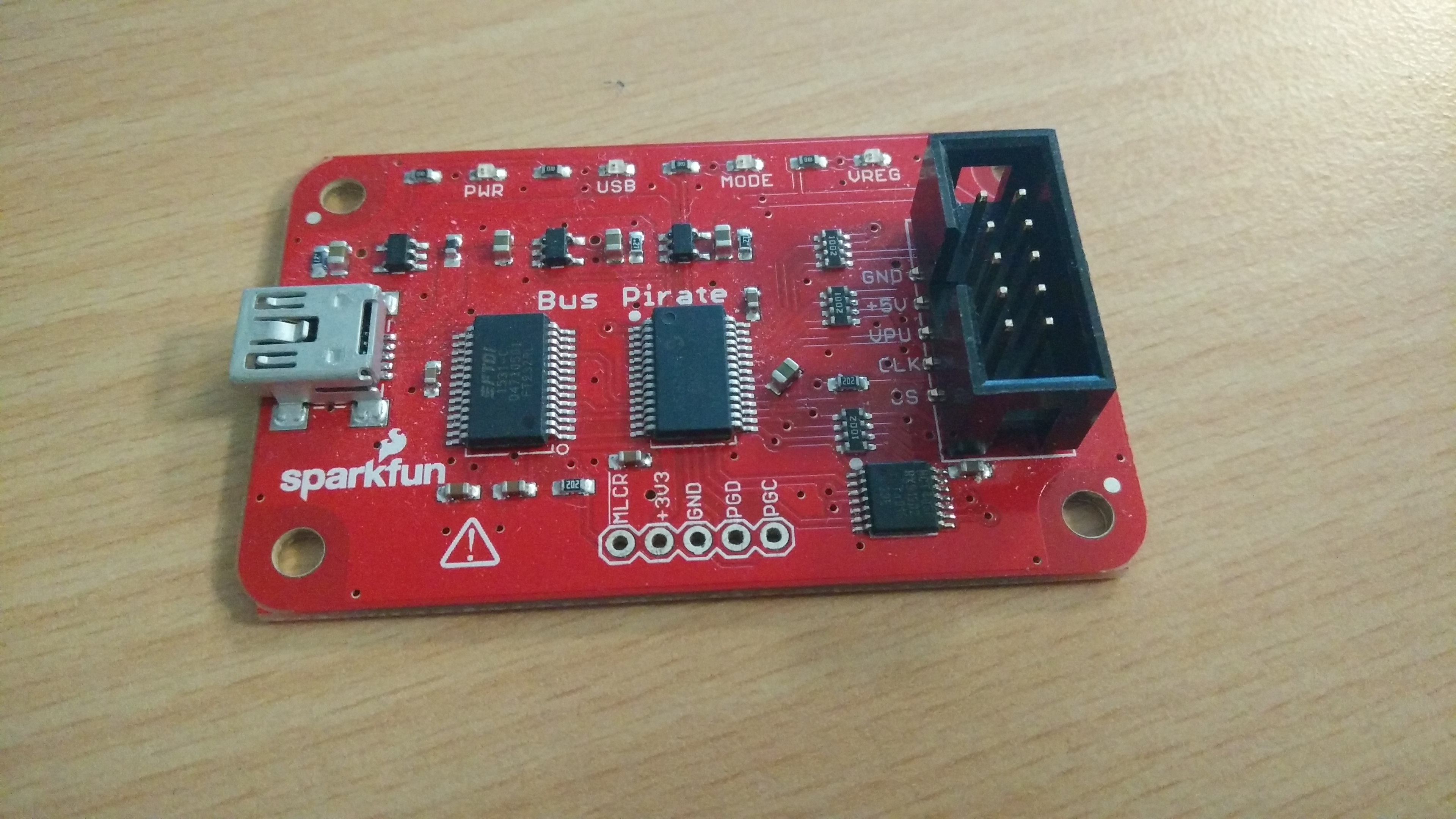
Bus pirate

The bus pirate is a small hardware board that provides an easy interfacing between your computer and some of most common protocols that we found in hardware communications, such as:
- UART
- JTAG
- SPI
- I²C
- And more…
It is useful for debugging, reading memories, sniffing data, writing data…
It has been developed by Dangerous Prototypes, you can find many resources and documentation there.
There are currently multiples versions of the bus pirate, I personally have the Bus Pirate v3.6 but the most recent one is the version 4. You can find the design improvement here, and a comparison between the two versions here.
The point that still bugs me with the v4 is that there is no support for JTAG over openOCD yet. Though it might come in a near future, I’d recommend ordering the version 3.6.
Cables
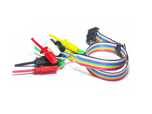
In order to properly work with this tool, you will need at least a USB cable with a USB mini B port and a set of cables/probes to attach to the device you want to test/comunicate with/attack.
I use this set of probes cables (which you can easily find online):

(source: http://dangerousprototypes.com/docs/images/1/1a/Seed-cable.png)
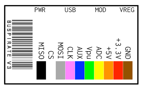
Here is the pinout of the cable:

(source: https://statics3.seeedstudio.com/images/probekit_LRG.jpg)
Anyway, that’s pretty much it for the hardware part, let’s start exploring what we can do with it!
Basic setup
First of all, we will require a bit of software setup to access the serial interface of the Bus Pirate.
Optional udev rule
If you are running a GNU/Linux distribution, you might want to follow this step.
The following udev rule is optional but is helpful and will speed up your everyday life when plugging the bus pirate into your computer.
Create the file /etc/udev/rules.d/98-buspirate.rules, containing the following:
SUBSYSTEM=="tty", ATTRS{idVendor}=="0403", ATTRS{idProduct}=="6001", GROUP="users", MODE="0666", SYMLINK+="buspirate"
What this does is that it matches the idVendor and idProduct of the bus pirate when you plug it in, and will create a symlink located at /dev/buspirate.
The interface will thus be available there, which is way simpler than finding what device was associated to your bus pirate.
(For example if you have multiple usb devices plug into your computer, it would either pop as /dev/ttyUSB0 or /dev/ttyUSB1 or other possible names. With this rule, no more issues, it will always be at /dev/buspirate).
You must then reload your udev rules, which can be done with this command (need to be root):
udevadm control --reload-rules
Talking to your BP
Many tools exist to communicate with the bus pirate’s serial interface, here’s a list of some of them:
I’ve used minicom for a while, but ended up using putty because it works both on Linux and Windows.
The setup for putty is simple enough:
Connexion type: Serial
Serial line: /dev/buspirate
Speed: 115200
You then have the possibility to save your configuration by writing a name in the box below Saved Sessions and then hitting the Save button.
Then, just double click the name you’ve chosen and a new terminal will open. (if you don’t see any prompt, try pressing enter, if that doesn’t work you may have a firmware issue)
The help command is the character ?:
 General                                        Protocol interaction
 ---------------------------------------------------------------------------
 ?      This help                       (0)     List current macros
 =X/|X  Converts X/reverse X            (x)     Macro x
 ~      Selftest                        [       Start
 #      Reset the BP                    ]       Stop
 $      Jump to bootloader              {       Start with read
 &/%    Delay 1 us/ms                   }       Stop
 a/A/@  AUXPIN (low/HI/READ)            "abc"   Send string
 b      Set baudrate                    123
 c/C    AUX assignment (aux/CS)         0x123
 d/D    Measure ADC (once/CONT.)        0b110   Send value
 f      Measure frequency               r       Read
 g/S    Generate PWM/Servo              /       CLK hi
 h      Commandhistory                  \       CLK lo
 i      Versioninfo/statusinfo          ^       CLK tick
 l/L    Bitorder (msb/LSB)              -       DAT hi
 m      Change mode                     _       DAT lo
 o      Set output type                 .       DAT read
 p/P    Pullup resistors (off/ON)       !       Bit read
 s      Script engine                   :       Repeat e.g. r:10
 v      Show volts/states               ;       Bits to read/write e.g. 0x55;2
 w/W    PSU (off/ON)            <x>/<x= >/<0>   Usermacro x/assign x/list all
You can then type i to display information about your board:
Bus Pirate v3.5
Firmware v6.1 r1676  Bootloader v4.4
DEVID:0x0447 REVID:0x3046 (24FJ64GA002 B8)
http://dangerousprototypes.com
I haven’t delved much in the different commands yet, but let’s move on to something a bit more interesting: communicating with the device you are trying to audit/hack.
Usage for UART
bus pirate configuration
One of the useful commands is the m command, which allows you to setup the BP for different modes. For this example, we’ll be using the UART mode.
So just type m at the prompt and hit enter.
1. HiZ
2. 1-WIRE
3. UART
4. I2C
5. SPI
6. 2WIRE
7. 3WIRE
8. LCD
x. exit(without change)
Choose option number 3. UART (just type 3).
Set serial port speed: (bps)
 1. 300
 2. 1200
 3. 2400
 4. 4800
 5. 9600
 6. 19200
 7. 38400
 8. 57600
 9. 115200
10. BRG raw value
You must now select the communication speed between the target and the bus pirate. Either you already know this value, either you will have to guess it. Or you will be able to let the BP determine it automatically later. So, if you know the speed just select the right one otherwise, choose at random!
You will then have to choose the settings for the connection. Usually, default settings work fine, but there are times when you will encounter a custom target which will force you to adapt.
Data bits and parity:
 1. 8, NONE *default
 2. 8, EVEN
 3. 8, ODD
 4. 9, NONE
(1)>
Stop bits:
 1. 1 *default
 2. 2
(1)>
Receive polarity:
 1. Idle 1 *default
 2. Idle 0
(1)>
Select output type:
 1. Open drain (H=Hi-Z, L=GND)
 2. Normal (H=3.3V, L=GND)

(1)>
Ready
Once everything is configured the BP will switch to UART mode. You can reset it to default by unpluging it or connecting the pins 3.3v to the GND on the side of the board (you can do this by swiping a piece of metal between the pins).
With the BP switched to a specific mode, you can now access the macro menu. In order to list the different available macro you must use the (0) command.
 0.Macro menu
 1.Transparent bridge
 2.Live monitor
 3.Bridge with flow control
 4.Auto Baud Detection
To execute a macro, you can use the (x) command, with x being the number corresponding to the macro you want.
As I previously mentioned, there is a macro that is used to detect the speed of the device (4.Auto Baud Detection), which is useful if you did not know the operating speed.
Once a macro is executed, depending on the one you chose, either will you be able to stop it and return to UART mode, or you won’t and will need to reset the BP.
But before we execute any macro, we must plug the BP into the target device.
cable configuration
To do so, you will need to locate the UART connector on your target, some are hidden, some aren’t, you might need a multimeter and a few datasheets to find them.
It can be shaped as pins or pads, or basically anything, good luck finding them! :)
The UART bus is made of just two wires: the receiver, RX, and the transmitter, TX. There should also be a PIN connected to GND, allowing the BP to know when the signal is down.
We will thus need 3 cables from the BP cable: MISO, MOSI and GND, which we will respectively plug onto the target:
| Bus Pirate | Target |
|---|---|
| MISO | RX |
| MOSI | TX |
| GND | GND |
When that’s done, you can use the macro from the latter step to start communicating from your computer to your target device.
UART interfaces are fun and all, you will sometimes find a tty, sometimes a custom prompt, maybe only a log activity… It has many applications which vary a lot between targets. However if we want do delve more into what’s running on our target (dumping a firmware, reading memories…), we might want to look at more interesting interfaces such as JTAG or SWD (unfortunately, the bus pirate doesn’t support SWD interfaces).
JTAG with openOCD
The JTAG interface is designed for debugging electronic systems, it can also be used to access registers or memory on a micro controller.
JTAG pinout
| Bus Pirate | Target |
|---|---|
| MISO | TDI |
| MOSI | TDO |
| CS | TMS |
| CLK | TCK |
| GND | GND |
OpenOCD installation and configuration
OpenOCD is a generic open source software.
The Open On-Chip Debugger (OpenOCD) aims to provide debugging, in-system programming and boundary-scan testing for embedded target devices.
Since it is generic, it can adapt itself to multiple processors and devices, but that requires a bit of configuration before being plug-n-play.
Installation
OpenOCD is an open source software, so if you’re running on a GNU/Linux system you’ll most likely find it in your distribution’s package list.
If you’re running on Windows no luck for you, you will find the package here.
Configuration
Configuring the interface
Firstly, we need to configure our interface (the bus pirate), in order to do so, create a file buspirate.cfg with the following content:
#
# Buspirate with OpenOCD support
#
# http://dangerousprototypes.com/bus-pirate-manual/
#

interface buspirate

# you need to specify port on which BP lives
# this can be /dev/ttyUSB0 or other,
# but if you added the udev rule it will display as
# /dev/buspirate.
buspirate_port /dev/buspirate

# communication speed setting
buspirate_speed normal ;# or fast

# voltage regulator Enabled = 1 Disabled = 0
buspirate_vreg 0

# pin mode normal or open-drain
buspirate_mode normal

# pullup state Enabled = 1 Disabled = 0
buspirate_pullup 0

# this depends on the cable, you are safe with this option
reset_config srst_only
Configuring the micro-controller
For this step, you will need to identify the micro-controller that is connected to your JTAG interface, then look into the target configuration files of OpenOCD to find the correct one.
The configuration files are either located in:
/usr/local/share/openocd/scripts/target/
or
/usr/share/openocd/scripts/target/
If you can’t find the file corresponding to your micro controller, well… You are out of luck and will need to provide it yourself. (Get a datasheet, get the documentation for OpenOCD, create your file and share it with the community!)
Usage
When you have both config files there is not much left to do, launch a terminal, and run openOCD with your configuration files. Please note that openocd is a daemon, you will need another terminal to connect to it (or you can run it in the background).
For example:
openocd -f buspirate.cfg -f /usr/local/share/openocd/scripts/target/stm32f2x.cfg
Then open another terminal and connect to openOCD’s interface using telnet or netcat.
nc localhost 4444
As a side note: I like to add the rlwrap command before nc, that allows us to have better line editing capabilities
From now, you can use the command help to list the different commands. It will be different for each micro-controller, so yeah, have fun, try stuff, discover…
Conclusion and alternatives
In conclusion, I’d say that it is a nice tool to have to mess around with IoT devices, it is easy to use, pretty cheap, and leaves room for improvement since it is open source.
However, it is slow, and I had some issues sniffing communications in I²C between a NOR memory and its micro-controller because the operating frequency of the IoT device was much higher than what the bus pirate can handle. A faster alternative called HardSploit is being developed by the French company Serma safety and security. I had the opportunity to try it out during a training, and I might make a post about it someday in the future. Currently, HardSploit have an open source community version, which costs around 300€. It’s not as cheap as the bus pirate, but it is more user friendly.
Another alternative I came across on the web is the HydraBus, which seems to be pretty interesting given all the protocols it can theoretically handle, the use of a Cortex M4 micro-controller and its measly price of $69. Unfortunately, I couldn’t test it yet.
That’s all for today, see you folks!
